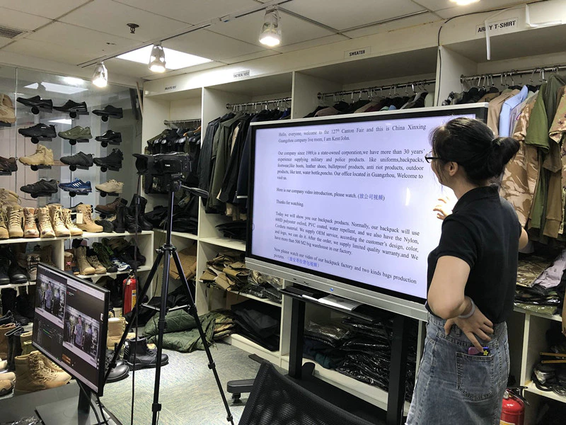
127TH Canton Fair Live Show
How to use 62 style compass
by:XinXing
2020-09-03
1. Purpose 6. The two-type compass is a simple measuring device for measuring azimuth, distance, level, slope (pitch angle), height, speed between marching, and simple maps for surveying and mapping. It is convenient to use at night and place it on each corresponding part. Coated with luminous powder. 2. Brief introduction of structure. The instrument is mainly composed of two parts: compass and odometer. The compass part has a lifting ring and a dial base. There are two kinds of markings on the dial base. The outer ring is a 360-degree division system, and each marking is 1 degree. The inner circle is a 6000 (closed) division system, and the circumference is engraved with 300 lines. The value of each engraved line is 20 (close position), and there are magnetic needles and goniometers inside. The unit of pitch angle is degree. Each reticle is 25 degrees. It can measure the pitch angle ±60 degrees. The odometer part is mainly composed of odometer, speed timetable, measuring wheel, gear pointer and so on. There are two scale scale values ??for mileage division: l: 50000 and l: 100000. The scale of 1:100000 corresponds to 1 km per engraved line. l: Each engraved line of 50000 represents 0.5 kilometers. It can be used with maps with corresponding scales or multiple scales. The speed timetable is divided into 13, 15, 17, 19, 21, 23, 25 km/h on the outer dial and 10, 14, 16, 18, 20, 22, 24, 30 km/h on the inner dial. (Represented by V), a total of 15 speeds. Each reticle in the time scale corresponds to 5 minutes (V25 is 10 minutes). There is a surveying ruler on the side of the instrument, and the two ends are distance estimators. The two tips of the estimator are 12.3 mm long, and the length between the sight and the sight is 123 mm. That is 10 times the tip length. 3. How to use (1) Measure the direction 1. Measure the direction of the site, southeast, northwest, (1) Turn on the compass. Align the azimuth indicator '△' with '〇'; (2) Rotate the compass. After the magnetic needle is pointed at the 'o' at the north end, the direction pointed at this time is north, and the directions of east, south, west and north can be directly read on the azimuth glass. 2. Calibrating the map position Calibrating the map position is to use the compass to make the position on the map consistent with the current position (1) Turn on the instrument and adjust the dial base to make the direction indicator '△' align with the magnetic deflection angle of the area; ( 2) Use the surveying ruler to be tangent to the true meridian or coordinate vertical line on the map (that is, the inner map outline of the east and west map outline); (3) Turn the map so that the north end of the magnetic needle points to 'O'', then the map is The location of the city is exactly the same as the current location. 3. Determine the magnetic azimuth A. Determine the magnetic azimuth of the target on the map (1) Use a compass to accurately calibrate the map and keep the map still; (2) Cut the surveying ruler to the line connecting the point and the target point, and adjust Dial base, make the index '△' align with the 'O' marking line; (3) After the magnetic needle is stationary, the scale on the dial base at the north end is the magnetic azimuth value from the point to the target point. B. Determine the magnetic azimuth angle of the target on the spot (1) Turn on the instrument, align the azimuth index '△' with 'O' and make the reflector and the dial seat slightly 45°; (2) Use your thumb to penetrate the lifting ring, Hold the instrument horizontally and aim at the target to be surveyed by the sight; (3) Looking at the scale on the dial base at the north end of the magnetic needle from the reflector is the magnetic azimuth value of the target on the spot. (2) Measure the distance 1. Use a surveying ruler to directly measure the distance on the map 2. Use the mileage to read the distance on the map (l) First return the red pointer to 'O'; (2) Hold the instrument horizontally and lighten the odometer wheel Place it on the starting point and scroll forward along the measured route to the end; (3) According to the engraved line pointed by the pointer on the scale, the corresponding actual distance can be read directly. For example, when measuring from point A to point B on a 1:50,000 map, and the scale of 1:50,000 on the surface of the instrument refers to 14 scribe lines, the field distance between points A and B is 7 kilometers. If 14 engraved lines are measured on a 1:100,000 map, the distance between A and B is 14 kilometers. In addition, maps with corresponding ratios (such as 1:25000) or multiple ratios (such as 1:20000 and 1:500,000) can also be read by conversion. Figure 2 position 3. Use a distance estimator to roughly measure the distance of the target on the spot. The distance between the two tips of the distance estimator on the instrument is 1/10 of the distance between the sight and the sight, and the distance of the target on the spot can be determined by using the similar triangle relationship. (1) Knowing the distance between the two targets (objects) and the point where they are located, the following formula can be used to find the distance between the two targets (objects): The distance between the two targets = the distance between the two targets and the standing point XI/10 Turn on the instrument and use your eyes to aim at the target. If two targets (objects) happen to be clamped by the two tips of the distance estimator (2) and the distance between the two target points and the point where they are known is 100 meters, then the two The distance between target points is 100X1/10=10 meters. The rest can be calculated by this method. In addition, when the distance between two targets (objects) in front is not necessarily clamped by the two tips of the distance estimator, but is smaller or larger than the gap, the following formula can be used: gap between two target points = two targets and where they are The distance between the points X1/10X the multiple of the distance between the two tips occupied by the two targets. Example: It is known that the distance between the two targets and the standing point is 100 meters, and the measured distance between the two targets is 7/ of the distance between the two tips of the distance estimator. 10, the distance between the two targets is: 100X1/10x710 = 7 meters. same. If the distance between the two targets is 1.5 times the distance between the two tips of the distance finder, the distance between the two targets is: 100X1/10X1.5=15 meters. (2) Knowing the width of the object or the distance between two targets, the distance between the target and the point can be calculated by the following formula: the distance between the target and the standing point = the distance between the known target X10 Example: the two fronts are known The distance between the targets is 12 meters, which is exactly the two tips of the distance estimator. The distance between the target point and the standing point is: 12x10=120 meters. In addition, if the distance between the target is known, but when aiming, it is less than or greater than the distance between the two tips of the distance estimator, the following formula can be used: the actual distance between the target X10 the distance between the target and the point = the target occupies the distance between the two tips of the estimator Multiples of the interval Note: The method of using a distance estimator to determine the distance to an on-site target is simple, but the accuracy is not high. (3) The speed timetable on the instrument for calculation of marching time and speed can measure the time required for marching or the marching speed within a specified time while measuring the mileage. The method is as follows: l, calculation of marching time: open Instrument to reset the odometer pointer to zero (red line on the dial). While calculating the mileage to the destination, the speed timetable is based on the scale of 1:100,000, indicating that it is 13, 15, 17, 19, 21, 23, 25 kilometers per hour (outside meter, clockwise reading) and 10 , 14, 16, 18, 20, 22, 24, 30 km/h, (inside meter, counterclockwise reading) the time required for the speed march. If it is the mileage measured on a map with a scale of 1:50000, tap the measuring wheel with your finger to halve the mileage, and the speed and time indicated by the pointer are what you want. For example: the distance measured on the 1:50000 scale map is 40 kilometers. If you walk the full distance at the speed of 'V20', find the required time. First, set the pointer to 20 kilometers on the scale of 1:50000, and the pointer in the V20 circle is what you want. If the specified speed is not on the watch For the displayed speed, find the speed that has a magnification relationship and multiply it by the magnification to find the time. For example, if the marching speed is 5 kilometers per hour, the measured mileage is 30 kilometers, and the time is calculated, you can read: 'V10' is 3 hours, Since 'V10' is twice V5, multiply the number by 2 or dial the measuring wheel to make the pointer indicate 60 kilometers to read V10 for 6 hours. If you read 'V6' when you read 'V18', multiply the number by 3 or dial test It takes 5 hours to read 'V18' when the wheel pointer indicates 90 kilometers, and so on. (Note: The above calculations do not include the marching rest, adjustment, and the slope and bending coefficient of the road measurement. When organizing the march, it should be in the table (Add relevant data above). 2. Marching speed calculation, while calculating the mileage to the destination, according to the required time limit, you can select the appropriate speed within the specified time limit according to the speed time calculation table (Note: if it is 1:50,000 The mileage of the scale should be selected by doubling the prescribed time limit) as the marching speed. (Note: When seeking the marching speed, add the relevant marching data to the corresponding calculation before calculating) (4) Measure the slope of the inclined plane (pitch angle) Turn on the instrument and make it reflect light The mirror and the dial base are slightly at 45 degrees, hold the instrument on its side, aim along the sight and the front sight to the side of the inclined plane, and make the aiming line parallel to the inclined plane, and allow the goniometer to swing freely. View the central engraved line of the goniometer from the mirror. Indicate the scale division on the pitch angle table, which is the desired pitch angle (slope). (5) Measure the approximate height of the target. The horizontal distance between the target (object) and the point where it is located, first determine the pitch angle of the target. Check the altimeter (see appendix 1) to get the height of the target. The method is as follows: 1. Find the location and target (such as mountain top, chimney, spire, etc.) from the map or using a distance estimator ) Horizontal distance. 2, hold the instrument sideways, aim along the sight, aim at the top of the target with the sight, let the goniometer swing freely, and see the pitch angle value indicated by the goniometer scribe line. 3, check the altimeter or use meters The height can be obtained by calculating the position formula. For example: the horizontal distance from the measuring point to the measured object is 100 meters, and the pitch angle is 30° measured with the instrument, then check the altimeter, and align the horizontal grid with 30° vertical grid at 100 meters , The height of the measured object was found to be 57.74 meters. IV. Maintenance and maintenance of the instrument 1. Do not place the instrument close to ferromagnetic materials to avoid loss of magnetism. 2. Do not hit the object with a surveying ruler to avoid affecting the measurement accuracy. 3. Mirror Do not twist, so as not to affect the aiming and reading division, the surface should be kept smooth, do not wipe with dirty cloth or hands. 4. The instrument should be closed when not in use. Put it in the box. Be careful not to collide.
Related Products